

Execution | Reliable Part Modelling 04
In this post we will imaging that you are finally ready to start modelling…
Before you start STOP! Let’s take a few minutes to plan our model. What do we need to consider before Execution?
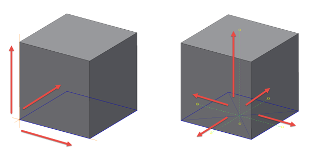
Center Point
In cartesian coordinates, the Center Point (or Origin) is the 0,0,0 point of your model.
Modelling around the origin allows us to reference the Center Point as a fixed datum, around which our part can change in a predictable fashion.
The center point may be in a different spot for every item you model, but it should be something you think about before your start modelling.
‘Where do I want the origin to end up, when I’ve finished modelling this thing?’
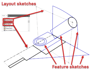
Layout Sketches
If anything goes wrong with your Inventor model, it’s likely to go wrong with a sketch.
When you learned Inventor – you were probably given the advice:
‘One sketch per feature’
This advice is meant to guarantee simple sketches, which only contain one closed loop. When you edit the design, Inventor is unlikely to pick the wrong loop if there is only one choice!
The downside of this technique is that single feature sketches are unrelated, which means that Design Intent is not captured.
The other extreme is overly complex shared sketches which can be difficult to edit and difficult to diagnose when things go wrong.
A layout sketch could be thought of as a ‘Skeleton’ which contains the main datums for a component.
Feature sketches are related to the layout sketch with projected geometry. When the layout sketch is driven by a parameter change, the features sketches go with it.
All sketches should be fully constrained.
There – I said it. You can take it from me. Quote me on this:
‘Fully constrained means fully predictable’.
If you’re sketches aren’t fully constrained, you can’t predict behaviour when you edit your component.
Note the indicator in the bottom right of the sketch environment to see how close you are to being fully constrained.
You may also notice a ‘push pin’ icon on your sketch nodes in the browser. This is a great way to check to see if a sketch is fully constrained without having to open the sketch first.
If you don’t know what you need to do to fully constrain your sketch, use the degree of freedom indicator or the Auto-dimensioning tool to help.
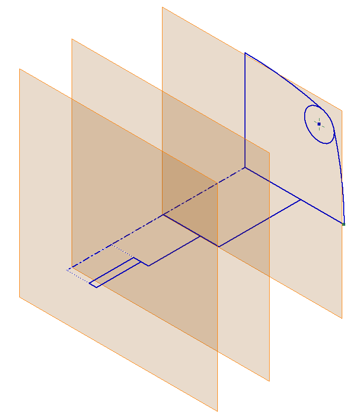
Datum Features
When we build a model by relating each sketch to the preceding feature, we can unintentionally build a house of cards.
When the Base Feature changes, all dependant sketches and features will also update. This can be extremely powerful (if this is what we intended) or extremely frustrating (when it isn’t).
Instead of basing a sketch on a feature, we can isolate the sketch from the preceding feature by basing the sketch on a datum plane. A datum plane can be a UCS, work plane or surface extrusion, which is driven by a named parameter or our layout sketch.
The link back to the layout sketch preserves Design Intent. The datum plane isolates the sketch from previous features, allowing us re-order the feature tree, or even delete features without upsetting our model.
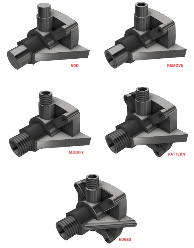
Feature build order
This idea of grouping similar features comes from Dick Gebhard’s ‘Resilient modelling strategy’. When I trained students using this technique we found maintaining feature groups to be problematic – features must be in the right order to get the desired result!
However, working through Dick’s exercises with my students, we found building your model with feature order in mind works well and can lead to better structured, more stable components.
Tip : Although you create the features in the following order, this is not necessarily the order which they will end up in the feature tree. Use the ‘End of Part Marker’ (EOP) to place features in the position they need to be for your desired result.
| Add > | Modify > | Remove > | Pattern > | Edges |
| Extrude | Draft | Trim | Mirror | Chamfer |
| Revolve | Shell | Hole | Pattern | Fillet |
| Thicken | Thread | Emboss | Concave before Convex | |
| Rib | Delete face | Big Before small | ||
| Sweep | ||||
| Loft | ||||
| Coil |
Feature grouping
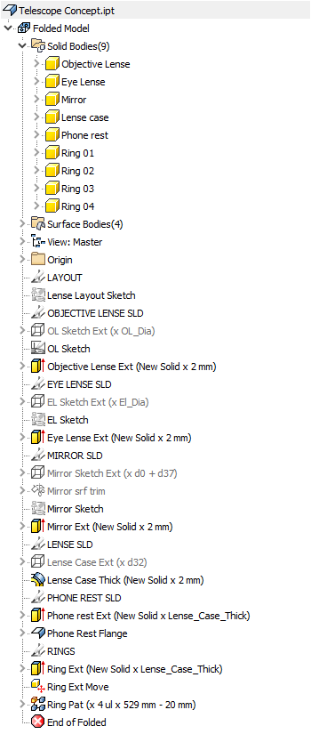
When working on a multibody file, it can be helpful to group features together that belong to the same body.
Sadly, we don’t have folders or feature grouping for the model browser in the Inventor part environment.
Instead I use 3D sketches, which I name in ALL CAPS and then turn their visibility off. This gives me just enough of a visual cue to be able to skim up and down the browser efficiently.
Flex your design
Test your designs! If you have invested effort building a component which can change over time – don’t simply assume that your model will update predictably!
Don’t forget, it could be you who must perform a quick Friday afternoon update to a model. No-one wants to be dealing with an exploding model when they have a deadline to meet.
I’ve stolen a term from Revit designers here, they call this testing ‘ Flexing’ the model.
Flex early, flex often, flush any unpredictable behaviour out of your design while the design intent is fresh in your memory.
It’s far more difficult to correct mistakes when you are revisiting a component after a few months working on other projects.
Communicating design intent
Well done for making it this far! Only one more post to go
Now you have built a reliable, parametric Inventor part model, how are you going to prevent you colleagues from messing it up!?
The answer is with good documentation. Before your model is complete, you need to spend some time communicating your design intent through good documentation – and that’s what we will discuss next…
Documentation | Reliable Part Modelling 05
This blog post is based on an Autodesk University class, by Luke Mihelcic and Paul Munford. You can watch a recording of the class, and download a handout that goes with this presentation from the Autodesk University website here:
MFG226705: Reliable Part Modeling Techniques for Complex Part Design in Inventor
Edit 2020/11/24
This class was updated and repeated for Autodesk University 2020
. You can find the revised version of the class, with video, handout, and dataset here:
‘Reliable Modeling Techniques for Complex Part Design in Inventor’ At AU2020
We also created a second part to the class: ‘ Reliable Techniques for Complex Assembly Design in Inventor
‘ – Here’s the link:
‘Reliable Techniques for Complex Assembly Design in Inventor’ at AU2020

The post Execution | Reliable Part Modelling 04 appeared first on Inventor Official Blog.


Industries


Sign Up to get our monthly news Letter
About Us
All Rights Reserved | Mitchell and Son Additive Manufacturing Ltd | Registered Company in England and Wales | Company Number : 12038697
| Public Liability Insurance no. 14615097
Insurer: AXA XL