

Singularities and Non-Manifold Topology | The Seven Deadly Sins of 3D Part Modeling 03
Have you ever tried to model a shape with Autodesk Inventor and failed? I have, many times!
In the previous post in this series, we learned about the 3D Modelling deadly sins of ‘Near Coincidence’ and ‘Sliver faces’ , and we learned how to avoid them!
In this post we’ll learn why Singularities are not a good thing, and we’ll understand how Inventor uses the concept of Manifold Topology to define our solid objects.
The 3D Modelling Deadly Sin of Singularities
In Part four of ‘Get Smart with Inventor Modelling’ we learned that the Autodesk Inventor Shape Manager (ASM) defines a loft as a four sided shape. ASM will fit the lofted surface to the profiles we supply.
If we supply three profiles, ASM will still return a surface, but the fourth edge will have collapsed into a single point .
This single point is called a Singularity . Singularities can also be formed when revolving a surface.
Singularities themselves aren’t a problem, but they can cause problems downstream, particularly when offsetting surfaces.
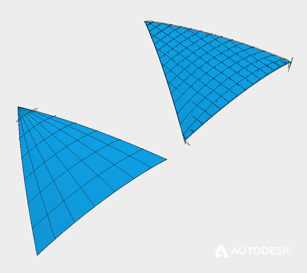
Detecting singularities in Autodesk Inventor using curvature comb analysis.
When you are having problems with a non-four-sided surface, the easiest way to diagnose Singularities is with the Curvature Comb Analysis Tool. If the combs converge on a single point – you have a singularity!
Whenever you can – try swapping the problem surface with a boundary patch . The boundary patch tool always creates a four-sided surface which is Trimmed to the input geometry (Instead of Fitted ), so singularities are avoided.
The 3D Modelling Deadly Sin of Non-Manifold topology
‘Manifold Topology’ describes how Inventor recognizes that a shape is a solid. If the shape is open Inventor will create a surface model. If the shape is closed Inventor knows that it has a solid.
There are four conditions that must meet met for a shape to be consider ‘closed’.
- Internal voids must be completely enclosed by faces.
- Faces must have an ‘inside’ and an ‘outside’.
- Each edge must only be shared by two faces.
- Each vertex must only be shared by three edges.
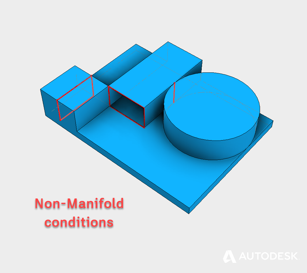
Examples of non-manifold geometry in an Autodesk Inventor Model
Any topology that breaks these rules is considered ‘Non-Manifold’, and we will struggle to get the results we need.
Non-Manifold topology causes ambiguities which Inventor can find confusing. The classic example is two cubes sharing an edge. This edge is non-manifold, because four faces are sharing the same edge.
When we try to fillet this edge, ambiguity arises because there are four equally valid solutions. Which one solution do we expect?
If you are having trouble with non-manifold geometry, try re-ordering the feature tree, creating multiple bodies or adding temporary supporting structure.
Loose Tolerances | The Seven Deadly Sins of 3D Part Modeling 04
In the next post in this series we’ll learn how and when to use the Loft Command, when to use a patch and why they are different.
This blog post is based on an Autodesk University class, originally by Jake Fowler and later updated by Inderjeet Wilkhu and Paul Munford. You can watch a recording of the class, and download a handout that goes with this presentation from the Autodesk University website here:
CP122682: The Inventor 7 Deadly Sins of 3D Part Modeling

The post Singularities and Non-Manifold Topology | The Seven Deadly Sins of 3D Part Modeling 03 appeared first on Inventor Official Blog.


