Autodesk Inventor’s AnyCAD Technology explained…

Part 1: The challenge of Product Design
I’ve been doing this for a while now… I promise I won’t subject you to any of those “back in my day” discourses, however, suffice it to say that my professional career began in the years BC. Not THAT BC, I’m not THAT old… rather BC as in Before CAD. Comprehensive system design required a lot more work then, as everything that was purchased or outsourced and used in a design had to be accurately drawn and represented in the assembly documents we were working on. That meant tracking down product catalogs, finding the specific component required, and then spending the time to recreate it, at scale, in our assembly documents. This was a frequent sight in the engineering department:
Think about this for a second… if you need accurate mass property calculations, and if you intend to perform any sort of dynamic assembly analysis, whether for determining overall system behavior, or for generating loads for subassembly or part level analysis, you have to have a very accurate geometric representation of the assemblies where those dynamic forces are generated. And this means the entire assembly, including those portions of it you “specified” rather than “designed”. Now… when is the last time you designed an angular contact or thrust bearing? For those of us who do not work for Timkin or SKF the answer to that question is most likely “never”. Depending on what it is that we design, odds are that at least 15-20% of our finished product will be comprised of components that we purchase or outsource. In the past, that meant a lot of time spent browsing component catalogs, like that poor fellow in the image above. With the advent of digital design tools, these tasks eased somewhat as we were all able to now store that work in a library, and reuse when possible. Further product developments, such as Inventor’s Content Center, ease this task somewhat, supplying users with fasteners, bearings, shaft components etc., and vendors have begun to make available digital downloads of their products, however, problems still exist in that any changes to the vendor supplied parts, require rework of that data.
A similar obstacle is faced by those companies in which different divisions utilize different design tools, yet spec and use components from those other divisions in their designs. Traditionally, for these companies, neutral file format transfer is the only solution for them with regard to sharing data between divisions. Similar to the purchased vendor data issue described previously, any changes to the source data require rework, some of it potentially significant if any local modifications have been made to that data.
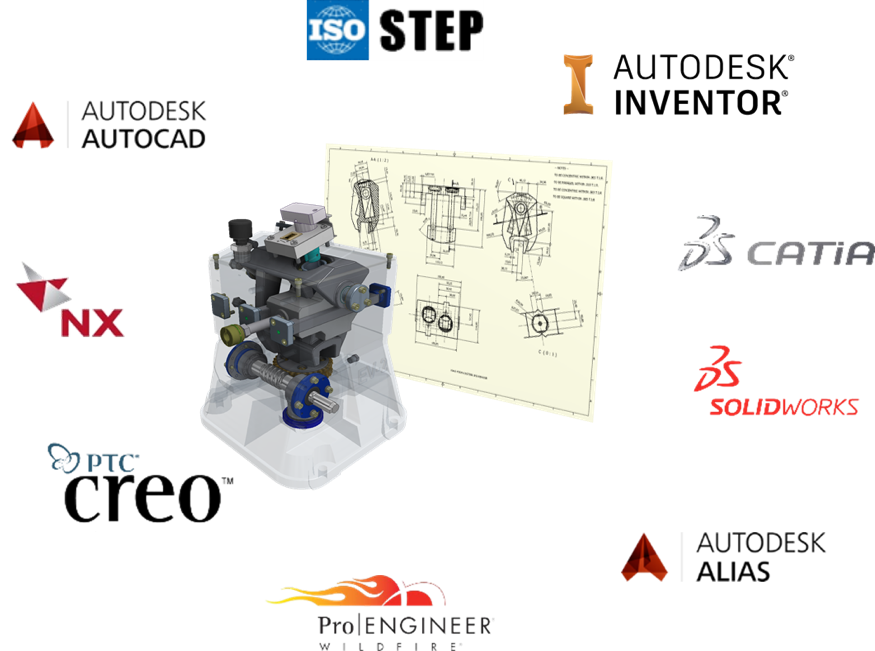
Autodesk AnyCAD technology is the solution to these problems. AnyCAD provides the ability to link to vendor data, negating the need for neutral file formats.
The advantage this provides is immediately obvious, especially to those users who fall into one of the two camps. As the AnyCAD link references the native vendor data, any change to that data via the original authoring tool results in a push through to the reference data used in the Inventor assembly file. AND, any local edits to that data in the .iam file are stored independently, and therefore, reapplied to the AnyCAD data, subsequent to an update.
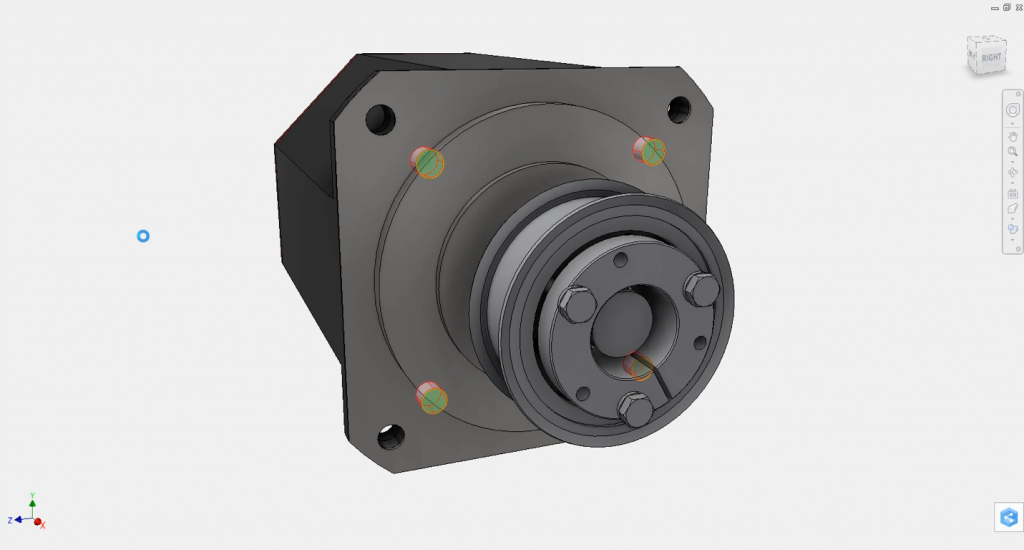
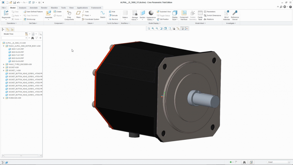
Here we have a servo motor, which is a native PTC Creo assembly, referenced in an Inventor assembly. It has been isolated, along with some of its mounting fasteners which are interfering with the location flange on the motor.
Cut features are added in Inventor to provide clearance for the fasteners… local editing of the referenced AnyCAD data. Problem solved.
At some point subsequent to this, the Servo Motor vendor makes a change to their motor design, using PTC Creo, their original authoring tool. Specifically, they add a relief cut to that same location flange we edited previously in Inventor.
The next time that assembly is opened in Inventor, the change to the vendor data is flagged, and the user is notified that an update is pending. Because the local edits are stored at the assembly level, independent of the referenced data, the change to the AnyCAD instance is processed, and then the local edits are performed on top of that.
The result is nothing short of magic, especially for those users, like myself, who prior to AnyCAD faced redundant changes post vendor data updates. If you are frequently tasked with this sort of data integration issues, I can’t recommend the AnyCAD workflow highly enough. Here’s the 2018 What’s New video of the workflow, as well as some additional AnyCAD functionality that I will be covering in Part 2 of this series.
Until then, Stay Gold Pony Boy!
Jay Tedeschi, Sr. Technical Marketing Specialist, BSM-D&M
The post Autodesk Inventor’s AnyCAD Technology explained… appeared first on Inventor Official Blog.
Industries


Sign Up to get our monthly news Letter
About Us
All Rights Reserved | Mitchell and Son Additive Manufacturing Ltd | Registered Company in England and Wales | Company Number : 12038697
| Public Liability Insurance no. 14615097
Insurer: AXA XL


