Inventor Tolerance Analysis

An assembly is only as good as the sum of its part tolerances, but traditional methods for considering tolerance stack-ups just don’t add up.
Excel sheets and manual calculations leave room for error. Producing physical prototypes creates a disconnect between the CAD model and test results, which poses a problem when the 2D drawing or 3D model are changed. But without methods for narrowing tolerance ranges early in the design process, machining processes that account for tolerances later on drastically increase manufacturing costs.
So how can engineers make informed, cost-effective decisions to ensure all the parts in an assembly will always go together while meeting performance requirements? That’s where the brand-new Autodesk Inventor Tolerance Analysis tool can help.
What is Tolerance Analysis?
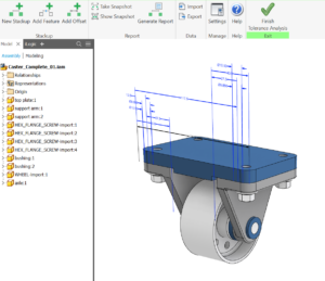
Inventor Tolerance Analysis is a CAD-embedded, 1D analysis solution that reports the mechanical fit and performance of designs based on dimensional tolerances. Stack-ups automatically capture the relationships defined in the assembly model – and for Model-Based Definition users, tolerance values can be edited directly inside the software to streamline the process between design and manufacturing.
With an in-canvas workflow that uses geometric dimensions and tolerances right on your model, analyze critical areas of your design to ensure they satisfy your objectives for manufacturing. Inventor Tolerance Analysis captures the necessary parts and mate relationships automatically to close the loop.
What else can it do?
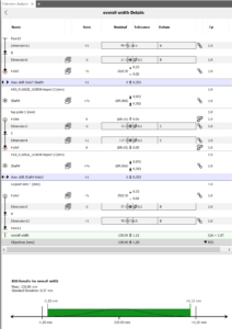
In the Tolerance Analysis panel inside Inventor, you’ll find immediate worst case and RSS results for dimensions that contribute to the stack-up, as well as bonus statistical results for Root Sum Square, Cpk, Sigma, DPMO, or Yield. Need to make changes to your tolerances? Due to the tight integration between Inventor and Tolerance Analysis, you can do so in the 3D model itself or within the Tolerance Analysis panel.
Then, quickly create a full report – including imagery, tolerance objectives and results, and a list of contributors and percentages for the stack-up – to communicate your findings to quality or manufacturing engineers.
Even if the model you’re analyzing was created in another CAD system, Inventor Tolerance Analysis uses AnyCAD to keep geometry in sync with model changes that could potentially impact results.
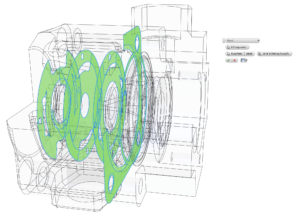
If you don’t have mates, dimensions, or tolerances, the Inventor Tolerance Analysis workflow will walk you step-by-step through the process of choosing the appropriate models and faces that contribute to the stackup while adding dimensions and default tolerances as needed to complete the analysis.
What’s the bottom line?
Inventor Tolerance Analysis helps your company save on costs by reducing waste, minimizing warranty issues, reducing physical prototypes, and getting your designs to production faster. By integrating testing early and often in the design process, engineers can explore more options and move to manufacturing sooner. This means you can get to your next project faster or put more focus on innovation by freeing up your engineering time.
Ready to get started?
 Inventor Tolerance Analysis is only available in the Product Design & Manufacturing Collection. Learn more about it here
– including how you can try it free.
 Makayla Millington
Autodesk Campaign Development Specialist
The post Inventor Tolerance Analysis appeared first on Inventor Official Blog.


