The Secrets of Lofting | Get Smart with Inventor Part Modelling 03

In this post, we’ll learn the Secrets of Lofting and how to get the best out of the loft command in Autodesk Inventor.
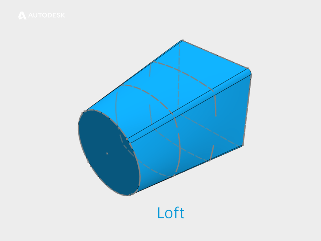
A Lofted shape
What does the Loft command do?
The Loft command creates a shape that is a smooth transition between two or more profiles .
Because the loft command can ‘warp’ the surface that it creates, we can set boundary conditions to maintain curvature continuity ( Click here to read Part 01 for a definition of curvature continuity ).
What is the difference between a Guide Rail and a Centreline?
A guide rail is doing the same job as a profile. The shape that we create is being ‘pulled’ toward the guide rails. We can have as many guide rails as we need.
A centreline behaves in a very similar way to a Sweep path. ASM will create intermediate profiles which will be perpendicular to the centreline. The profiles will follow the path, instead of being ‘pulled’ toward it.
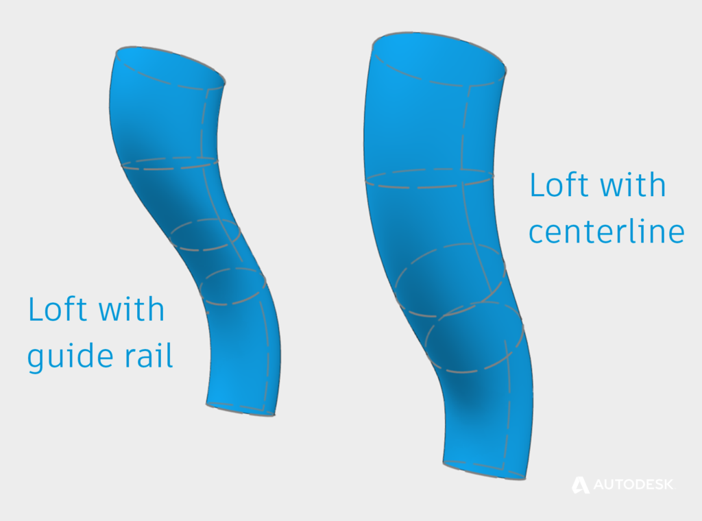
Lofting with Guide Rail Vs Lofting with Centerline
When would I use a Centreline loft, instead of Guide rails?
A centreline loft with a pair of profiles will give you a naturally smooth transition. If you are struggling to get what you need from a rail loft, try centreline instead.
When SHOULDN’T I use a Loft?
Lofts can be created from sketches, faces, and points as inputs, but they are limited to a minimum of two profiles.
What if we want to create a surface using only one input? Maybe it’s time to learn about Patch?
What’s the difference between a Loft and a Patch? | Get Smart with Inventor Part Modelling 04
This blog post is based on an Autodesk University class, originally by Jake Fowler and later updated by Inderjeet Wilkhu and Paul Munford. You can watch a recording of the class, and download a handout that goes with this presentation from the Autodesk University website here:
CP122682: The Inventor 7 Deadly Sins of 3D Part Modeling
The post The Secrets of Lofting | Get Smart with Inventor Part Modelling 03 appeared first on Inventor Official Blog.


